Desalination / TDS Removal
Salt removal & water recovery up to zero liquid discharge
What this application solves
High dissolved-salt content limits reuse and breaches discharge limits. WFS designs desalination of brackish, process and treated-wastewater streams using membrane and thermal technologies, with brine management up to full zero liquid discharge (ZLD).
Robust pretreatment is the key to membrane reliability; for very high TDS or ZLD, membranes are combined with brine concentrators, evaporators and crystallizers to recover maximum water and produce a dry solid.
Typical influent characteristics
| Parameter | Typical range |
|---|---|
| TDS (in) | 1,000 – 70,000 mg/L |
| Hardness | 100 – 2,000 mg/L CaCO₃ |
| Silica | 5 – 150 mg/L |
| SDI₁₅ | < 5 (required) |
| Flow | 5 – 1,000 m³/h |
These ranges frame the design basis. WFS confirms the exact values for your site through laboratory characterization and 24-hour composite sampling, capturing variability across normal, upset and turnaround operation before any equipment is sized.
The problems — and how WFS solves them
- Membrane scaling (CaCO₃, CaSO₄, silica) & fouling
- High osmotic pressure / energy at high TDS
- Brine / reject management & disposal
- Achieving high recovery and ZLD economically
- Maintaining stable low-SDI feed
- Strong pretreatment (UF, softening, antiscalant)
- Single / two-pass RO and high-recovery RO
- Electrodialysis reversal (EDR) for select streams
- Brine concentrators & evaporators
- Crystallizers for ZLD solids
Targets the system is designed to meet
| Performance parameter | Design target |
|---|---|
| TDS (permeate) | < 50 – 500 mg/L |
| Salt rejection | > 98 – 99.5% |
| Recovery (RO) | 75 – 90% |
| ZLD recovery | > 95 – 99% |
Guaranteed, tested performance
Every WFS system is commissioned against a documented performance test. We design to the discharge consent, reuse specification or zero-liquid-discharge target — and verify it on site before handover, then sustain it through O&M.
Filtration approach & system required
Recovery is pushed in stages — conventional RO, then high-recovery RO on the reject, then thermal concentration — so that each technology works in its most economical range. Antiscalant and softening keep sparingly-soluble salts in solution.
For ZLD, the membrane reject feeds an evaporator/crystallizer that recovers the last of the water and yields a disposable solid, eliminating liquid discharge.
- Ultrafiltration / softening pretreatment
- Reverse osmosis trains (single/two-pass/HRRO)
- Electrodialysis reversal (optional)
- Brine concentrator / evaporator
- Crystallizer & solids handling (ZLD)
Modular process-train schematic
- 1PretreatmentUF / softening + antiscalant
Deliver stable low-SDI feed
- 2Primary ROSingle / two-pass RO
Bulk salt removal
- 3High-Recovery ROBrine-concentrator RO / EDR
Recover water from reject
- 4Thermal ConcentrationEvaporator / brine concentrator
Concentrate residual brine
- 5CrystallizationCrystallizer (ZLD)
Recover water, produce solids
Indicative system specification
Layout & general arrangement
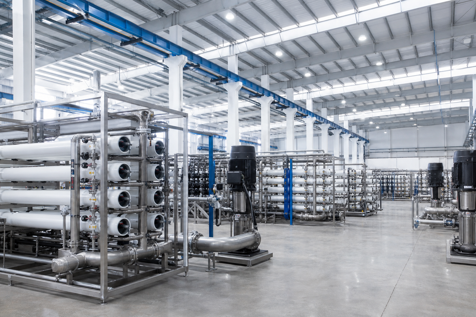
Pretreatment and RO skids occupy a covered membrane hall; high-pressure pumps and energy-recovery devices are grouped for piping efficiency. The thermal/ZLD block (evaporator, crystallizer) is a separate, taller area with steam supply.
Permeate, reject and solids routing are clearly segregated; CIP and chemical storage are centralized with safe access.
- 01Pretreatment
- 02Primary RO
- 03High-Recovery RO
- 04Thermal Concentration
- 05Crystallization
What WFS delivers
- 1Feed-water analysis, scaling & recovery study
- 2RO / EDR / ZLD process design & projection
- 3Pilot verification of flux & recovery (if required)
- 4Membrane & thermal system fabrication
- 5Installation, tie-ins & ZLD construction
- 6Automation, commissioning & performance test
- 7O&M, membrane management & service
From study to continuous O&M
- 01Study & Assess
- 02Characterize Water
- 03Custom Design
- 04Pilot & Trial
- 05Detailed Engineering
- 06Equipment Design
- 07Fabricate
- 08Deliver to Site
- 09Construct
- 10Electrical & Automation
- 11Continuous O&M
Discuss your desalination / tds removal project
Share your stream data and target specification — WFS will characterize the water and propose a custom train.