Solids / TSS Removal from Wastewater
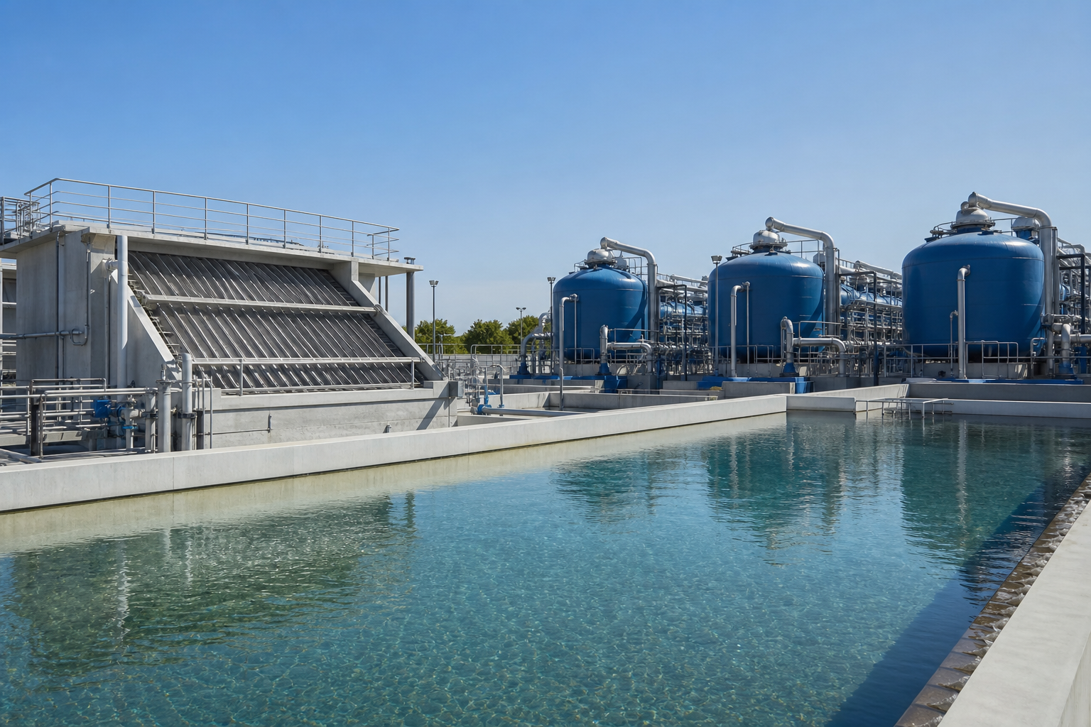
Clear water — suspended-solids removal from inlet to polish
What this application solves
Suspended solids — silt, scale, catalyst fines, coke, biological floc and precipitates — foul equipment, blind membranes, and carry oil and metals. WFS designs solids-removal stages sized to particle size and concentration, from gross settling to sub-micron filtration.
Solids removal is frequently the protective front end for membranes, ion exchange and reuse systems, so reliability and low residual turbidity are the design priorities.
Typical influent characteristics
| Parameter | Typical range |
|---|---|
| TSS (in) | 50 – 5,000 mg/L |
| Turbidity | 10 – 500 NTU |
| Particle size | sub-µm – mm |
| Flow | 5 – 1,500 m³/h |
These ranges frame the design basis. WFS confirms the exact values for your site through laboratory characterization and 24-hour composite sampling, capturing variability across normal, upset and turnaround operation before any equipment is sized.
The problems — and how WFS solves them
- Wide particle-size distribution
- Fine and colloidal solids that resist settling
- Variable solids load & shock turbidity
- Protecting downstream membranes (low SDI)
- Sludge handling & dewatering
- Coagulation / flocculation conditioning
- Lamella / tube-settler clarification
- Dissolved air flotation for light solids
- Multimedia & disc / screen filtration
- Ultrafiltration for absolute, low-SDI polish
Targets the system is designed to meet
| Performance parameter | Design target |
|---|---|
| TSS (out) | < 5 – 10 mg/L |
| Turbidity | < 0.5 – 1 NTU |
| SDI₁₅ (UF) | < 3 |
| Filtration rating | down to 0.02 µm (UF) |
Guaranteed, tested performance
Every WFS system is commissioned against a documented performance test. We design to the discharge consent, reuse specification or zero-liquid-discharge target — and verify it on site before handover, then sustain it through O&M.
Filtration approach & system required
Coagulation conditions fine and colloidal solids so they can be settled, floated or filtered. The clarification method (lamella vs DAF) is chosen by solids density; filtration then polishes to the turbidity / SDI the downstream stage needs.
Where the target is membrane protection, ultrafiltration provides an absolute barrier independent of inlet variability.
- Coagulation / flocculation package
- Lamella clarifier / DAF unit
- Multimedia / disc / screen filters
- Ultrafiltration skids
- Sludge thickener & dewatering
Modular process-train schematic
- 1ConditioningCoagulation / flocculation
Agglomerate fine solids
- 2ClarificationLamella / tube settler / DAF
Bulk solids separation
- 3Media FiltrationMultimedia / disc / screen
Reduce residual TSS & turbidity
- 4Membrane PolishUltrafiltration
Absolute barrier, low SDI
- 5Sludge HandlingThickener + dewatering
Concentrate & cake solids
Indicative system specification
Layout & general arrangement
Conditioning and clarification at the inlet, filtration skids in a line, and UF as the final barrier before the downstream user. Sludge from the clarifier and filter backwash routes to a common dewatering area.
Backwash recovery is included to minimize water loss; the layout supports modular expansion of filter trains.
- 01Conditioning
- 02Clarification
- 03Media Filtration
- 04Membrane Polish
- 05Sludge Handling
What WFS delivers
- 1Solids / particle-size characterization
- 2Clarification & filtration design basis
- 3Equipment fabrication & supply
- 4Installation, backwash & sludge routing
- 5Automation, commissioning & performance test
- 6Downstream-protection (SDI) verification
- 7O&M & media/membrane management
From study to continuous O&M
- 01Study & Assess
- 02Characterize Water
- 03Custom Design
- 04Pilot & Trial
- 05Detailed Engineering
- 06Equipment Design
- 07Fabricate
- 08Deliver to Site
- 09Construct
- 10Electrical & Automation
- 11Continuous O&M
Discuss your solids / tss removal from wastewater project
Share your stream data and target specification — WFS will characterize the water and propose a custom train.