Spent Caustic Treatment
Safe oxidation & neutralization of high-strength spent caustic
What this application solves
Spent caustic from LPG, gasoline and olefins treating is one of the most hazardous refinery streams — high pH, high COD, sulfides, mercaptans, phenolics and odor. It cannot be sent directly to biological treatment. WFS designs dedicated pre-treatment that destroys sulfides and reduces COD before polishing.
Depending on the caustic type (sulfidic, naphthenic, cresylic), WFS applies wet air oxidation, chemical oxidation, neutralization with acid-gas stripping, or acidification with hydrocarbon recovery.
Typical influent characteristics
| Parameter | Typical range |
|---|---|
| pH | 12 – 14 |
| Sulfides | 1,000 – 40,000 mg/L |
| COD | 20,000 – 200,000 mg/L |
| Phenols | 1,000 – 20,000 mg/L |
| Caustic (NaOH) | 2 – 12 wt% |
These ranges frame the design basis. WFS confirms the exact values for your site through laboratory characterization and 24-hour composite sampling, capturing variability across normal, upset and turnaround operation before any equipment is sized.
The problems — and how WFS solves them
- Extremely high COD, sulfide and phenol loads
- Severe odor (H₂S / mercaptans) and corrosivity
- Hazard and safety risk in handling and reaction
- Wide variability between caustic types
- Protecting the biological plant from shock & toxicity
- Wet Air Oxidation (WAO) for high-strength sulfidic caustic
- Catalyzed chemical oxidation (air / peroxide) for lower strength
- Neutralization with controlled acid-gas stripping & scrubbing
- Acidification with hydrocarbon / cresylic acid recovery
- Buffered, metered feed of treated stream to the ETP
Targets the system is designed to meet
| Performance parameter | Design target |
|---|---|
| Sulfide | < 1 mg/L (oxidized) |
| COD reduction | 70 – 99% |
| Effluent | biodegradable, ETP-compatible |
| Odor / H₂S | scrubbed to safe level |
Guaranteed, tested performance
Every WFS system is commissioned against a documented performance test. We design to the discharge consent, reuse specification or zero-liquid-discharge target — and verify it on site before handover, then sustain it through O&M.
Filtration approach & system required
Oxidation is the core: it converts toxic sulfides to harmless sulfate/thiosulfate and breaks down organics. The route (WAO vs catalytic vs neutralization) is matched to strength, sulfur form and recovery value.
Off-gas is fully scrubbed and the treated liquid is buffered and dosed slowly into the ETP so the biology is never shocked.
- Blanketed storage / buffer tanks
- Wet air oxidation or catalytic oxidation reactor
- Neutralization & acid-gas stripping unit
- Off-gas scrubber package
- Recovery / phase-separation skid (optional)
- Corrosion-resistant pumps & instrumentation
Modular process-train schematic
- 1Storage & BufferingAgitated, blanketed tank
Stabilize variable feed
- 2OxidationWet air / catalytic oxidation
Destroy sulfides, cut COD
- 3NeutralizationAcid dosing + stripping
Adjust pH, release/strip gas
- 4Gas ScrubbingCaustic / amine scrubber
Capture H₂S & odor
- 5Recovery (optional)Phase separation
Recover cresylic acid / HC
- 6Equalized DischargeMetered feed to ETP
Protect biological plant
Indicative system specification
Layout & general arrangement
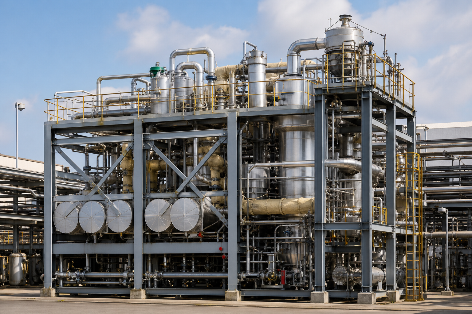
A segregated, bunded hazardous-area block: blanketed storage, the oxidation reactor with heat-recovery exchangers, neutralization and a dedicated scrubber stack. Spacing and classification follow hazardous-area and toxic-gas standards.
Safety systems — gas detection, relief, emergency quench and showers — are integral. The treated-stream tie-in to the ETP is metered and interlocked.
- 01Storage & Buffering
- 02Oxidation
- 03Neutralization
- 04Gas Scrubbing
- 05Recovery (optional)
- 06Equalized Discharge
What WFS delivers
- 1Spent caustic characterization by type
- 2Technology selection (WAO / oxidation / neutralization)
- 3HAZOP-reviewed process & safety design
- 4Reactor, scrubber & neutralization fabrication
- 5Installation, hazardous-area E&I & interlocks
- 6Commissioning, performance & emissions testing
- 7O&M, safety procedures & operator training
From study to continuous O&M
- 01Study & Assess
- 02Characterize Water
- 03Custom Design
- 04Pilot & Trial
- 05Detailed Engineering
- 06Equipment Design
- 07Fabricate
- 08Deliver to Site
- 09Construct
- 10Electrical & Automation
- 11Continuous O&M
Discuss your spent caustic treatment project
Share your stream data and target specification — WFS will characterize the water and propose a custom train.