Turnaround Wastewater Treatment
Mobile, fast-deploy treatment for shutdown & turnaround peaks
What this application solves
Turnarounds (TARs) generate large, short-duration volumes of contaminated water from equipment cleaning, hydro-jetting, decontamination and chemical cleaning — heavily loaded with oil, solids, spent chemicals and high COD. This water often cannot enter the normal ETP without upsetting it.
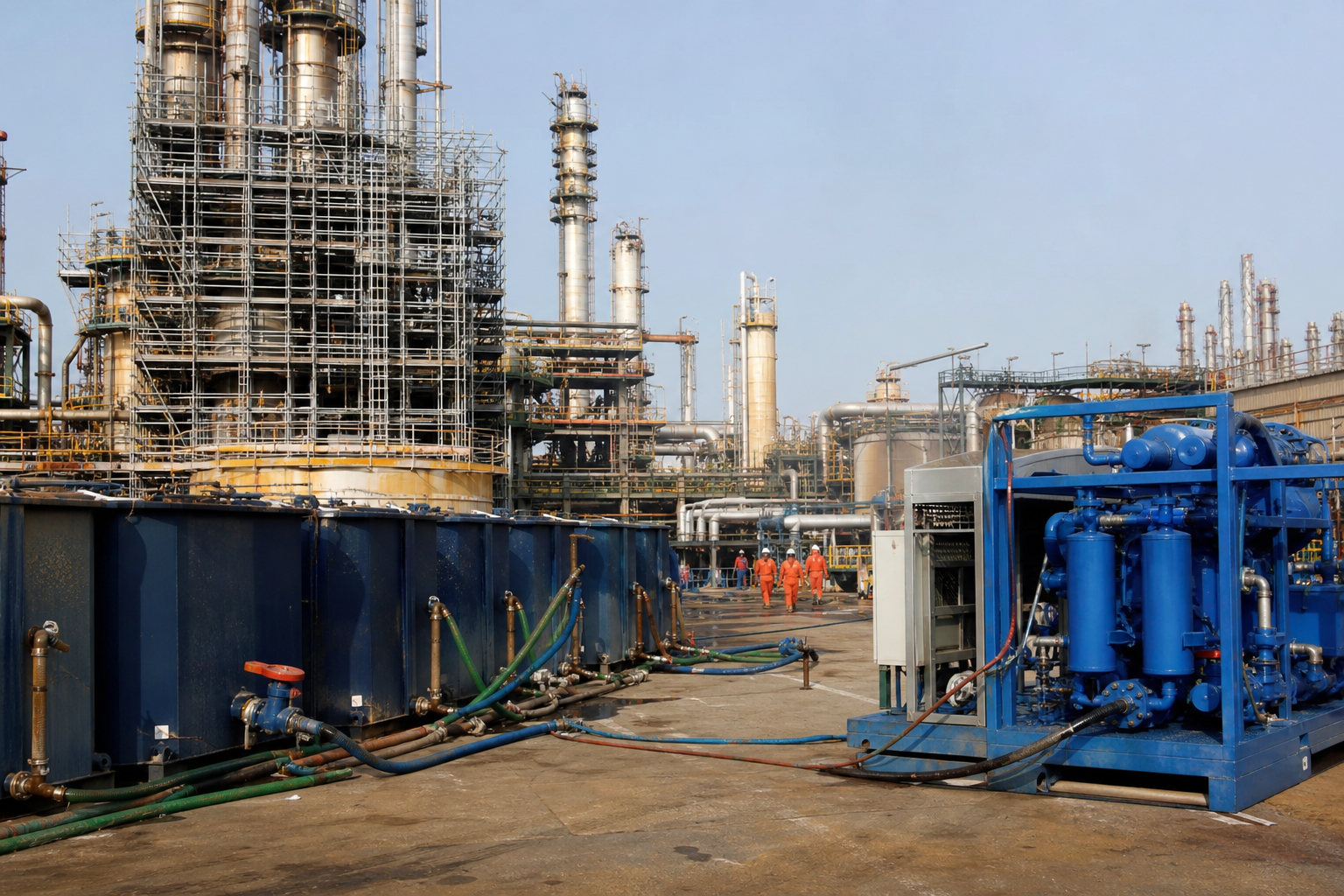
WFS provides containerized, trailer-mounted treatment trains that are mobilized to site for the TAR window, treating the peak load on-site and protecting the permanent plant, then demobilized.
Typical influent characteristics
| Parameter | Typical range |
|---|---|
| Flow (peak) | 20 – 500 m³/h |
| Oil & Grease | 500 – 10,000 mg/L |
| TSS | 500 – 20,000 mg/L |
| COD | 2,000 – 30,000 mg/L |
| Solids / sludge | high, variable % |
These ranges frame the design basis. WFS confirms the exact values for your site through laboratory characterization and 24-hour composite sampling, capturing variability across normal, upset and turnaround operation before any equipment is sized.
The problems — and how WFS solves them
- Very high, intermittent volumes over a compressed schedule
- Extreme and variable contaminant loads
- No permanent footprint available on the live plant
- Short mobilization windows and strict EHS interfaces
- Heavy solids and sludge requiring dewatering & disposal
- Containerized / trailer-mounted modular treatment units
- Frac / buffer tanks for surge storage and equalization
- High-rate coagulation, flotation and filtration
- Mobile dewatering (filter press / decanter) for sludge
- Rapid mobilization, operation and demobilization by WFS crews
Targets the system is designed to meet
| Performance parameter | Design target |
|---|---|
| Oil & Grease | < 10 mg/L |
| TSS | < 30 mg/L |
| COD | meets ETP inlet / discharge spec |
| Throughput | matched to TAR schedule |
Guaranteed, tested performance
Every WFS system is commissioned against a documented performance test. We design to the discharge consent, reuse specification or zero-liquid-discharge target — and verify it on site before handover, then sustain it through O&M.
Filtration approach & system required
Surge storage is the foundation — frac tanks decouple erratic generation from steady treatment. Treatment then runs as a robust, chemically-assisted physical train designed for the worst-case load.
All units are plug-and-play skids with quick-connect hoses, allowing layout to flex around the live plant and the TAR footprint.
- Frac / buffer storage tanks
- Containerized oil-removal & flotation units
- Mobile coagulation / flocculation skids
- Bag, media and ultrafiltration packages
- Mobile filter press / centrifuge
- Transfer pumps, hoses & manifolds
Modular process-train schematic
- 1Surge StorageFrac / buffer tanks
Equalize peak volumes
- 2Oil RemovalMobile CPI + IGF/DAF
Strip free & emulsified oil
- 3CoagulationInline dosing + reactor
Destabilize solids & emulsions
- 4FiltrationBag / media / UF skids
Remove residual solids
- 5PolishingActivated carbon
Reduce dissolved organics
- 6Sludge DewateringFilter press / decanter
Cake for disposal
Indicative system specification
Layout & general arrangement
A laydown-yard layout: storage tanks at the inlet, treatment containers in series, dewatering and roll-off bins at the outlet, all linked by lay-flat hose. The arrangement is set to suit each TAR's available space and crane/truck access.
Bunded areas and spill containment are provided around every unit to meet live-plant EHS requirements.
- 01Surge Storage
- 02Oil Removal
- 03Coagulation
- 04Filtration
- 05Polishing
- 06Sludge Dewatering
What WFS delivers
- 1TAR water management & volume estimate
- 2Mobile treatment design & equipment schedule
- 3Mobilization, installation & EHS interface
- 4Operated treatment through the TAR window
- 5Sludge dewatering & disposal logistics
- 6Demobilization & site restoration
- 7Treatment & disposal documentation / manifests
From study to continuous O&M
- 01Study & Assess
- 02Characterize Water
- 03Custom Design
- 04Pilot & Trial
- 05Detailed Engineering
- 06Equipment Design
- 07Fabricate
- 08Deliver to Site
- 09Construct
- 10Electrical & Automation
- 11Continuous O&M
Discuss your turnaround wastewater treatment project
Share your stream data and target specification — WFS will characterize the water and propose a custom train.