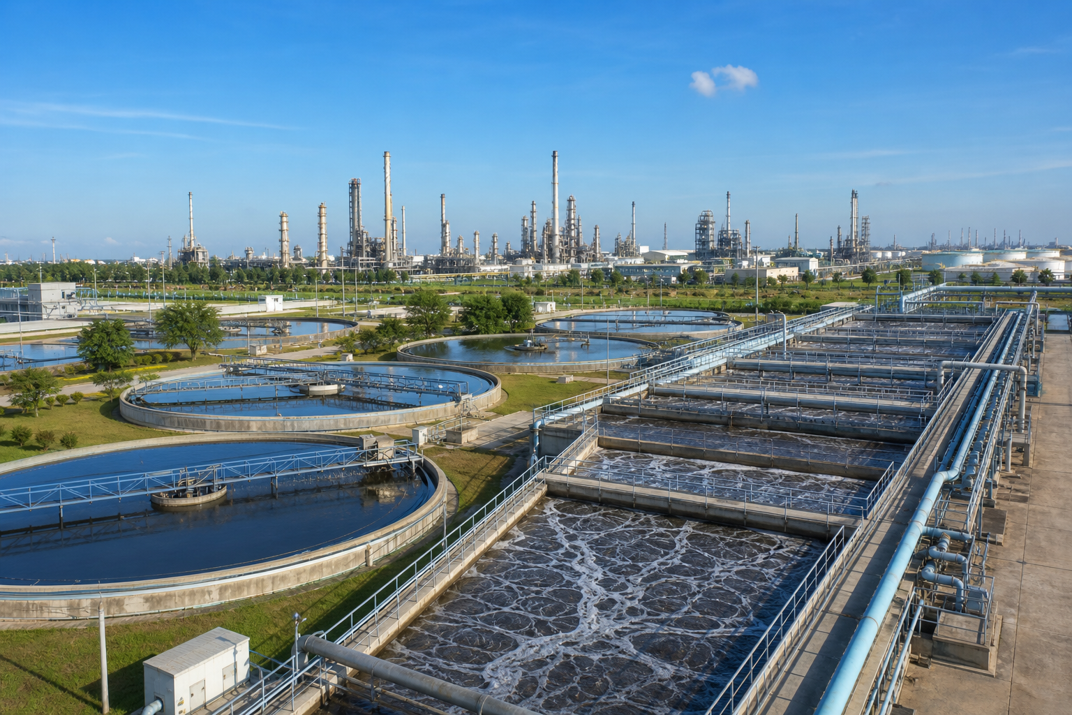
Wastewater Treatment Plant
End-to-end effluent treatment from sump to discharge or reuse
What this application solves
A petrochemical or refinery Effluent Treatment Plant (ETP) must handle a highly variable, multi-stream wastewater containing free and emulsified oil, suspended solids, dissolved organics (COD/BOD), phenols, sulfides, ammonia, heavy metals and high TDS. WFS designs the full treatment train — primary oil and solids removal, secondary biological oxidation, and tertiary polishing — sized to the site's specific flow and load profile.
Each plant is built around a verified water characterization and mass balance so that every unit operation is correctly loaded. The result is a robust, automated facility that consistently meets discharge consent limits or produces reuse-grade water for cooling make-up, irrigation or boiler feed.
Typical influent characteristics
| Parameter | Typical range |
|---|---|
| Flow | 50 – 2,000 m³/h |
| COD | 500 – 5,000 mg/L |
| BOD₅ | 200 – 2,000 mg/L |
| Oil & Grease | 50 – 2,000 mg/L |
| TSS | 100 – 1,500 mg/L |
| Phenols | 5 – 200 mg/L |
| Ammonia-N | 10 – 150 mg/L |
| TDS | 1,000 – 35,000 mg/L |
These ranges frame the design basis. WFS confirms the exact values for your site through laboratory characterization and 24-hour composite sampling, capturing variability across normal, upset and turnaround operation before any equipment is sized.
The problems — and how WFS solves them
- Highly variable flow and shock organic / oil loads from upset and turnaround events
- Emulsified oil and surfactants that resist gravity separation
- Toxicity (phenols, sulfides, cyanides) inhibiting biological treatment
- Refractory COD that is hard to oxidize biologically
- Tight, falling discharge limits and reuse / ZLD mandates
- Equalization with mixing and buffering to dampen shock loads
- Two-stage oil removal: API/CPI separation followed by induced/dissolved air flotation
- Biological treatment (MBBR, conventional or membrane bioreactor) tuned for toxicity
- Tertiary polishing — media / ultrafiltration, activated carbon and advanced oxidation
- Optional RO + evaporator/crystallizer for reuse or zero liquid discharge
Targets the system is designed to meet
| Performance parameter | Design target |
|---|---|
| COD | < 100 – 150 mg/L |
| BOD₅ | < 10 – 30 mg/L |
| Oil & Grease | < 5 – 10 mg/L |
| TSS | < 10 – 30 mg/L |
| Phenols | < 0.5 mg/L |
| Recovery (reuse) | 75 – 95% |
Guaranteed, tested performance
Every WFS system is commissioned against a documented performance test. We design to the discharge consent, reuse specification or zero-liquid-discharge target — and verify it on site before handover, then sustain it through O&M.
Filtration approach & system required
The train is staged by contaminant: gross oil and solids first, then dissolved organics, then dissolved salts. This protects downstream membranes and minimizes chemical and energy cost.
Filtration moves from coarse to fine — screening and separation, dual-media and multimedia filtration, ultrafiltration as an absolute barrier ahead of reverse osmosis, and final guard cartridge filtration.
- Oil-water separators (API / corrugated plate interceptor)
- Dissolved / induced gas flotation packages
- Biological reactor (MBBR / MBR skids or basins)
- Multimedia & ultrafiltration skids
- Activated carbon and advanced oxidation units
- Sludge thickening & dewatering (decanter / filter press)
Modular process-train schematic
- 1Screening & EqualizationBar/drum screens + buffer tank
Remove debris, balance flow & load
- 2Primary Oil RemovalAPI / CPI separator
Gravity separation of free oil & solids
- 3FlotationIGF / DAF + coagulation
Remove emulsified oil & fine solids
- 4BiologicalMBBR / MBR / activated sludge
Oxidize COD, BOD, phenols, ammonia
- 5Tertiary FiltrationMultimedia / Ultrafiltration
Polish TSS & turbidity
- 6PolishingGAC + advanced oxidation
Remove refractory COD & color
- 7Desalination (optional)RO + ZLD
Recover water, concentrate brine
Indicative system specification
Layout & general arrangement
A linear hydraulic-profile layout lets flow move by gravity where possible, minimizing pumping. Primary separation and flotation sit close to the inlet sump; biological basins occupy the largest footprint; tertiary skids and the RO/ZLD block are containerized or housed.
Sludge handling is grouped near dewatering with truck access. Chemical dosing, blowers, MCC/control room and laboratory are arranged for safe operator routing and maintenance clearance.
- 01Screening & Equalization
- 02Primary Oil Removal
- 03Flotation
- 04Biological
- 05Tertiary Filtration
- 06Polishing
- 07Desalination (optional)
What WFS delivers
- 1Water characterization, mass balance & process design basis
- 2Treatability / pilot study report (if required)
- 3PFDs, P&IDs, hydraulic profile & general arrangement
- 4Fabricated and installed equipment train
- 5Civil, mechanical, piping, electrical & instrumentation works
- 6PLC/SCADA automation, commissioning & performance test
- 7O&M manuals, operator training & long-term service contract
From study to continuous O&M
- 01Study & Assess
- 02Characterize Water
- 03Custom Design
- 04Pilot & Trial
- 05Detailed Engineering
- 06Equipment Design
- 07Fabricate
- 08Deliver to Site
- 09Construct
- 10Electrical & Automation
- 11Continuous O&M
Discuss your wastewater treatment plant project
Share your stream data and target specification — WFS will characterize the water and propose a custom train.