API Separator API
Bulk gravity oil–water–solids separation. Gravity-based rectangular basin that separates bulk free oil, settleable solids and water by density difference — the robust first stage of nearly every oily-water train.
System Schematic
Representative process-flow — configured to your streamUnderlying Technology & Scientific Principle
The American Petroleum Institute (API) separator works on Stokes' Law: in a quiescent rectangular basin, free oil droplets larger than ~150 µm rise to the surface while heavier solids settle, driven purely by the density difference between oil, water and grit.
Working Mechanism
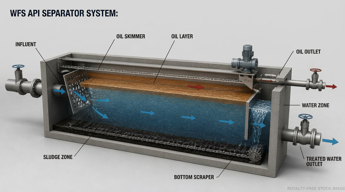
Oily water enters through a distribution baffle that calms turbulence and spreads flow across the full cross-section. As water travels the length of the basin at low horizontal velocity, buoyant oil collects as a surface layer skimmed by a slotted pipe or rotating skimmer, while settled sludge is scraped by a chain-and-flight collector to a hopper for withdrawal.
Separation / Removal Efficiency
Removes essentially all free oil (>150 µm) and reduces oil-and-grease to roughly 50–150 mg/L. It does not address chemically emulsified or dissolved oil, which require downstream stages.
Operating Principle & Parameters
Sized by Stokes' rise rate and a length-to-width ratio of typically 4:1–5:1; surface loading 0.5–1.0 m/h. Horizontal velocity held below 15× the oil-rise velocity (≤0.015 m/s) to prevent re-entrainment.
Flow Rates & Volumetric Capacities
Single basins handle 50–1,500 m³/h; multi-bay units serve full-refinery effluent above 2,000 m³/h. Robust to hydraulic slugs and variable oil loading.
Fluid Media Compatibility
Carbon-steel or concrete basins with oil-resistant coatings; FRP internals. Compatible with hot, saline, sour and high-solids streams across upstream, midstream and downstream service.
System Schematic & Process Integration
Always the lead unit ahead of CPI packs, DAF, flotation or biological treatment. Recovered oil is routed to slop-oil recovery; sludge to dewatering.
Options / Variations Available
Open or covered (VOC-controlled) basins; single or multi-channel; chain-and-flight vs. bridge-mounted scrapers; optional pre-separation flash mixing.
System Complexity & Automation Level
Low complexity — level-actuated skimming, timed sludge scraping and interface monitoring. Easily integrated into plant SCADA via level and oil-interface sensors.
Applications & Performance Delivered
Refinery & petrochemical effluent
Lead de-oiling stage; recovers slop oil and protects all downstream treatment.
Tank-farm & terminal drainage
Handles rain-driven slugs and tank-bottom draws with stable separation.
Produced-water pre-treatment
Knocks out bulk free oil ahead of hydrocyclones or flotation.
Contaminant Removal Profile
Continue exploring the train
 Primary
Corrugated Plate Interceptor
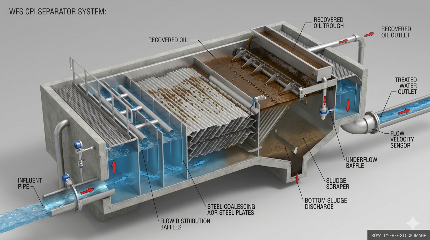
CPIInclined corrugated-plate pack that shortens the distance an oil droplet must rise — delivering API-class separation in a fraction of the footprint.
Explore technology →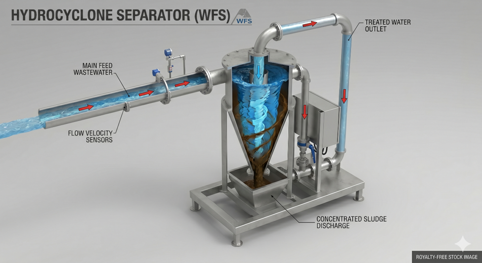 Primary
Hydrocyclones
HCStatic centrifugal de-oilers that spin produced water at thousands of g — separating dispersed oil with no moving parts in a compact, deck-friendly package.
Explore technology →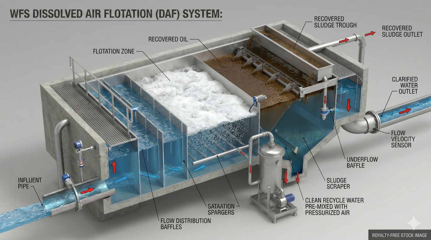 Secondary
Dissolved Air Flotation
DAFMicro-bubble flotation that lifts emulsified oil, light solids and chemical floc to the surface — the workhorse secondary de-oiler for emulsified streams.
Explore technology →