Moving Bed Biofilm Reactor MBBR
High-rate biofilm on free-moving carriers. Continuous biofilm process on floating plastic carriers — high biomass, small footprint and strong resilience to toxic and load shocks.
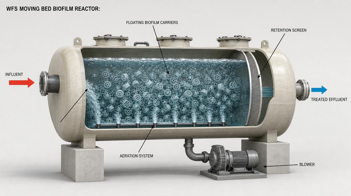
System Schematic
Representative process-flow — configured to your streamUnderlying Technology & Scientific Principle
The Moving Bed Biofilm Reactor (MBBR) combines the best of activated-sludge and fixed-film processes: free-floating plastic carriers (specific surface area 500–1200 m²/m³) are suspended in an aerated tank by coarse-bubble aeration. Biomass grows as a thin biofilm on the carriers' protected internal surfaces, giving high active biomass per reactor volume without recycle.
Working Mechanism
Wastewater flows continuously through the tank with the carriers fluidised by aeration (aerobic) or mixers (anoxic/anaerobic). Sieves at the outlet retain carriers in the tank. Biofilm on the carriers degrades organics, nitrifies ammonia and (in anoxic stages) denitrifies — without sludge recycle or settling within the reactor itself.
Separation / Removal Efficiency
BOD/COD removal 80–95%; ammonia nitrification >95% at 5–25 °C; total nitrogen removal 70–85% in pre-denitrification configurations; resilient to 2–5× load shocks and toxic spikes.
Operating Principle & Parameters
Carrier fill 30–67% by volume; HRT 1–6 h; DO 2–4 mg/L (aerobic) or <0.5 mg/L (anoxic); temperature 5–35 °C; pH 6.5–8.5; no MLSS control or sludge recycle required.
Flow Rates & Volumetric Capacities
From compact 1 m³/h package plants to >50,000 m³/d municipal trains; easy retrofit into existing aeration basins by adding carriers and sieves.
Fluid Media Compatibility
HDPE or PE carriers (AnoxKaldnes K1/K3/K5 style) with protected internal surface area 500–1200 m²/m³; coarse-bubble aeration grid; outlet sieves (wedge-wire or perforated plate).
System Schematic & Process Integration
Refinery and petrochemical wastewater BOD/nitrification, municipal upgrades, pre-treatment ahead of MBR or activated sludge, IFAS hybrid configurations.
Options / Variations Available
Pure MBBR or IFAS (Integrated Fixed-Film Activated Sludge); single-stage carbon removal or multi-stage C/N/dN trains; aerobic/anoxic/anaerobic carrier mixes.
System Complexity & Automation Level
Medium — DO control, blower turndown, online ammonia/nitrate monitoring; no sludge-age or RAS control required.
Applications & Performance Delivered
Refinery wastewater
Robust BOD removal and nitrification on variable, occasionally toxic feeds.
Municipal upgrade (IFAS)
Doubles capacity of existing aeration basins without footprint expansion.
Pre-treatment to MBR/RO
Reduces organic load and ammonia ahead of membrane polishing.
Contaminant Removal Profile
Continue exploring the train
 Polishing
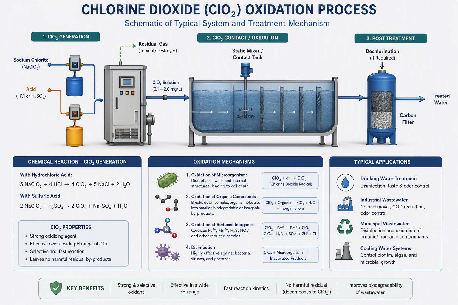
Chlorine Dioxide (ClO₂) Treatment
ClO₂A powerful selective oxidant and biocide dosed on-site — controls biofouling and oxidises sulphides without forming chlorinated by-products.
Explore technology →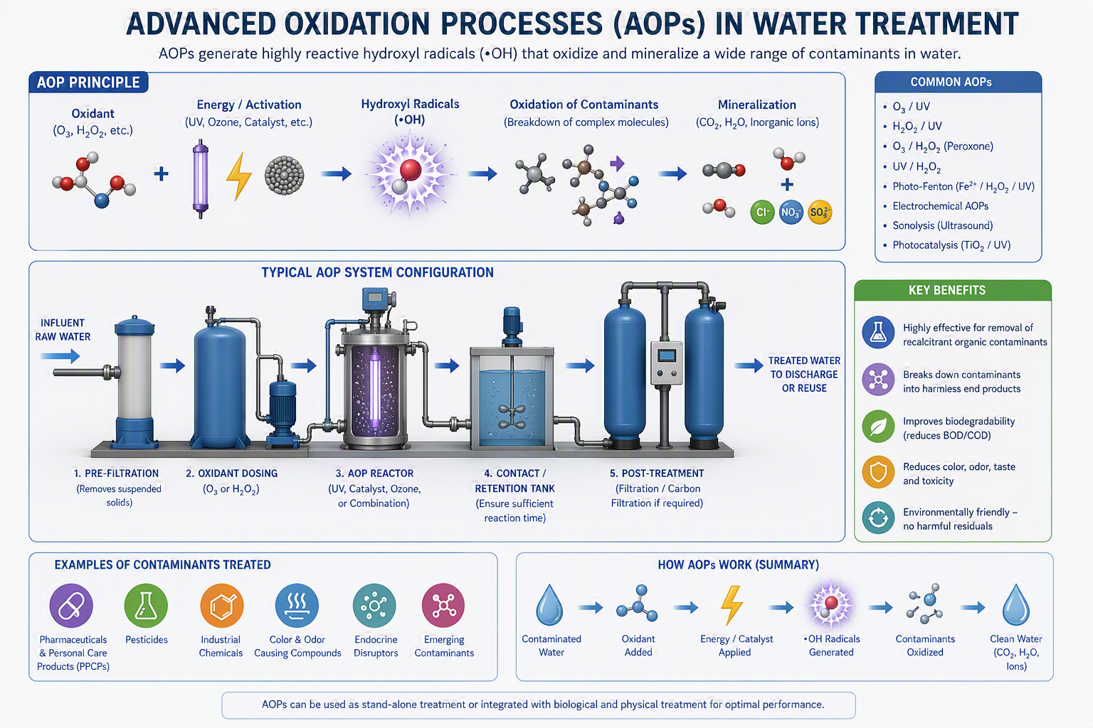 Polishing
Advanced Oxidation Processes
AOPHydroxyl-radical generation (UV/ozone/peroxide/Fenton) that destroys the most persistent organics outright — mineralising what other processes only transfer.
Explore technology →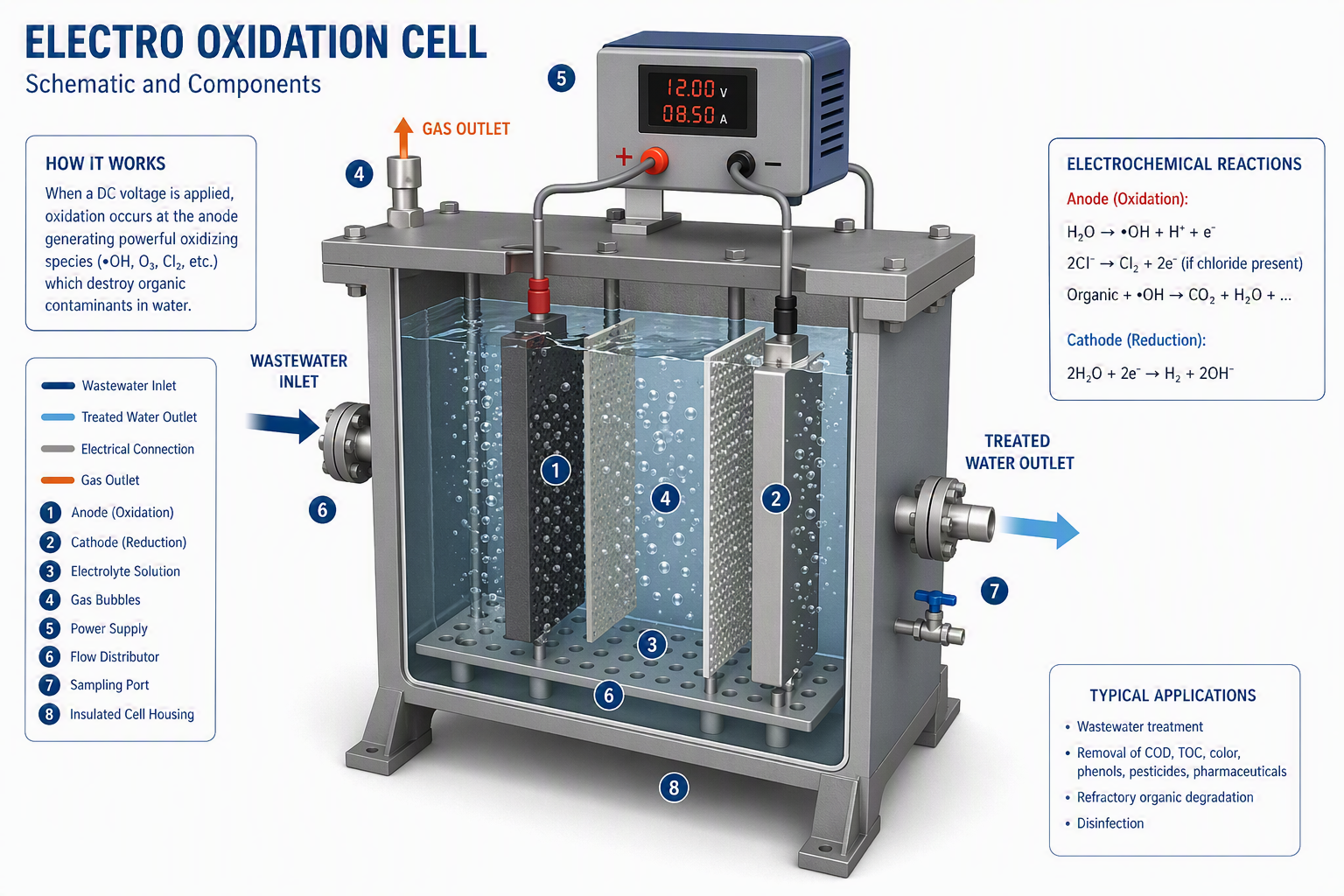 Polishing
Electro-oxidation
EODirect anodic oxidation at dimensionally stable electrodes that destroys refractory organics and ammonia in high-salinity brines — chemical-free advanced oxidation.
Explore technology →